Quick Reference Guide (QRG) #10
Last updated24 January 2025
Pairing 2nd Generation Remote Transmitters with 2nd Generation Ignition-Lock motor 4270P, using External RF Receiver Module 216P
IMPORTANT: Ignition Lock motors are installed to enhance the safety while driving and are generally only controlled through a dash switch. Operating cockpit shades by RF remote transmitter is not recommended and is only to be used in exceptional cases for drivers with disabilities who could otherwise not reach the dash switch when the vehicles is parked and in “living mode”. RF Remote Transmitters are never to be used in the cockpit area while the vehicle is in motion!
This manual will guide you through the process of replacing a 2nd Generation Ignition Lock motor that is being controlled through one of the 2nd Generation Remote Transmitters. This requires a separate RF Receiver Conversion Module (216P) to pick up and understand the signal sent out by the existing remote transmitter.
Wiring of RF Receiver Module 217P
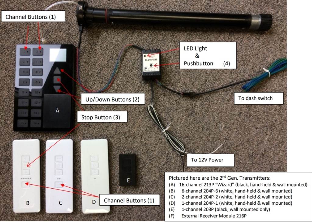
This external Conversion Module is only to be used with 2nd generation AMS RF Remote Transmitters (203P, 204P, 213P).
Pairing of RF Receiver Module 216P with 2nd Generation RF Remote Transmitters
-
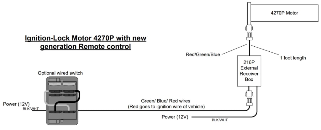
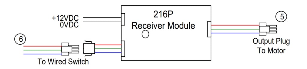
Connect the output plug of the External Receiver Module (5) to Motor, and input plug to the wires coming from the wired dash switch that controls the shade (6). The red wire connects to ignition wire of vehicle.
- Ensure the Module is connected to a 12V DC power supply (white wire to ground, black wire to 12V power). A green light on the Module should now be lit.
- Follow the instructions on QRG #7-2 to set the limits on 4270P motor.
- On the Remote RF Transmitter, select and press the appropriate channel (1).
- On the External Receiver Module, press and hold the pushbutton (4) until the color of the LED light changes to red, then release it and immediately, using a pin, press and hold the pairing button on the back of remote transmitter for few seconds (small pin-hole on the back of every transmitter), then release it and immediately press the stop button (3) on your remote transmitter.
Note: On the 16-Channel transmitter “SET” will appear on the display window after you have pressed the pair button long enough, at which time you can release the pair button.
Other Technical Notes:
Note 1:
To clear or un-pair a channel on the remote, press and hold the pairing (pin-hole) button on the back of the remote transmitter for few seconds (16-Channel remote: until “SET” appears on the display window), then press “down” button on the front of the remote transmitter.
Note 2:
If the shade moves up when you press down, press and hold the pairing (pin-hole) button on the back of the remote transmitter for few seconds (16-Channel remote: until “SET” appears on the display window), then press “up” button on the front of the remote transmitter.
Note 3:
Illustration (6) above shows the 3 wires with input plug coming from the dash switch that connecting to Module 216P. For full wiring instructions of Dash-Switch to Module 216P, refer to Quick Reference Guide QRG #5-2.