
Quick Reference Guide (QRG) #16
Motor ReplacementReplacement of tubular motor in electrical House Shade
Last updated12 September 2023
Replacing of House Shade Motors 1st and 2nd Generation Standard Motors 4280 and 4280P
This manual will guide you through the process of replacing motor(s) in a Windshield Shade showing the steps after you have removed the complete shade assembly from your vehicle’s ceiling pocket. All illustrations below show the motor side of the shade, which is where you will notice the power cables.
To remove the motor from its aluminum tube, you will have to carefully follow the steps below:
- Remove the spring clip (1): This clip needs to be removed to be able to open the motor bracket. Be careful when pushing this spring clip off its bracket as it could easily jump into your face. Use caution and hold a piece of cloth around the bracket to catch the clip it when it pops off.
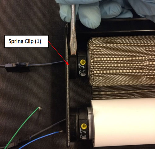
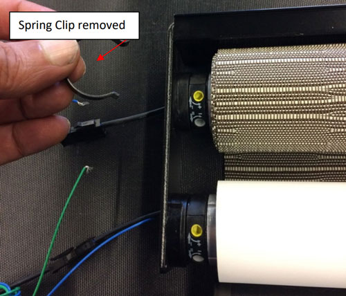
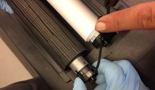
- Open the “Locking Latch” (2) that holds the motor axle in place, as shown in the picture below.
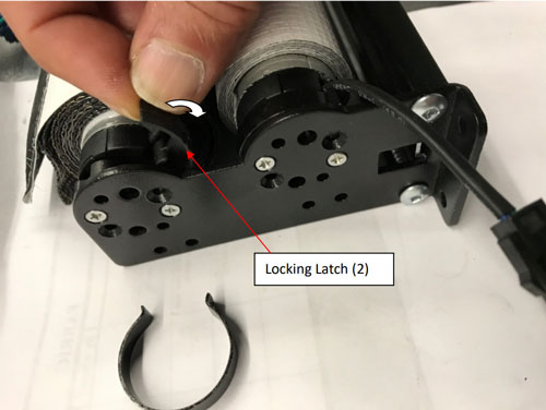
- While holding the shade tube(s) firmly with your hand to prevent it from dropping out of the opposite bracket(s), slide the motor head out of the locking latch as shown.
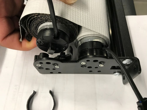
- Hold both shade tubes firmly in place while gently pulling the motor(s) out of the aluminum tube(s).
If you feel resistance and the motor(s) do not seem to move, do not force it as your motor(s) could be of an earlier generation prior to 2015/16 where motors were still held in place by a screw (not visible as under fabric). In such case, stop immediately and follow the below instructions, which will show you how to proceed in removing motors that are fixed with such screw. (Important: your new replacement motor(s) no longer requires such a screw!)
If you realize that you cannot pull the motor out of its aluminum tube, it is because on first generation motors the motor drive was secured with a screw driven from the outside of the aluminum tube (see below illustration).
To remove this screw, you need to completely unroll the fabric until you reach the point where the fabric is taped to the aluminum tube and only one wrap of fabric is left on the tube; do not remove the fabric any further! Now about 11”-12” in from the edge of the tube you will feel over the fabric with your finger to locate the small hole of a countersunk screw on the tube underneath the fabric.
With a sharp knife cut out a tiny bit of fabric over the screw, then remove the screw and discard it. DO NOT try to refit this screw after you inserted the new replacement motor! This screw is no longer needed and trying to use it through the same hole could severely damage the motor and render it inoperable.
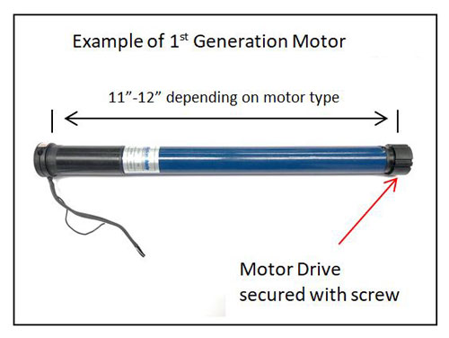
1st generation motor with motor drive screwed to aluminum tube. - Installing the new motor back into aluminum tube:
When inserting the replacement motor(s) of the standard type 4280P back into the tube, you will need to align the motor collar with the tube slots as shown in the illustration below. If you are installing an Ignition-Lock Motor 4270P, no such alignment is needed. You can skip this step for 4270P motor.
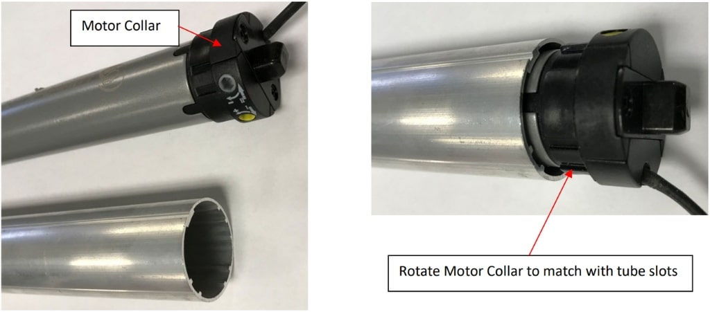
On newer motor models produced after 2015/16, a modified collar version was used that can no longer be inserted the wrong way into the aluminum tube. However, on older generation motors, this alignment is very important as otherwise the motor could very slightly shift inside the tube during operation and thus intermittently loose its accurate limit position.
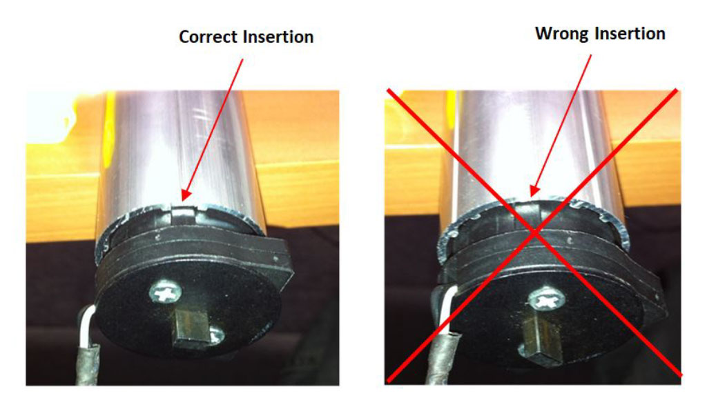
When inserting the motor into the aluminum tube, make sure the small nose on the motor collar is fitted in-between the two aluminum ribs that are close together (“Correct Insertion”).
-14.jpg)
- To install the motor(s) back into the shade, follow all above steps in reverse order.
IMPORTANT: When inserting the motor tube(s) into their bracket, make sure that the limit adjustment screw(s) will be accessible from below when you install the shade assembly into the frame of the coach. If they are not easily accessible, you may have to rotate the motor nozzle(s) in its bracket(s). - After you have re-installed the shade to its original location, you will have to readjust the upper and lower limit positions. Please refer to QRG #2 for setting limits.