Quick Reference Guide (QRG) #12
Last updated12 September 2023
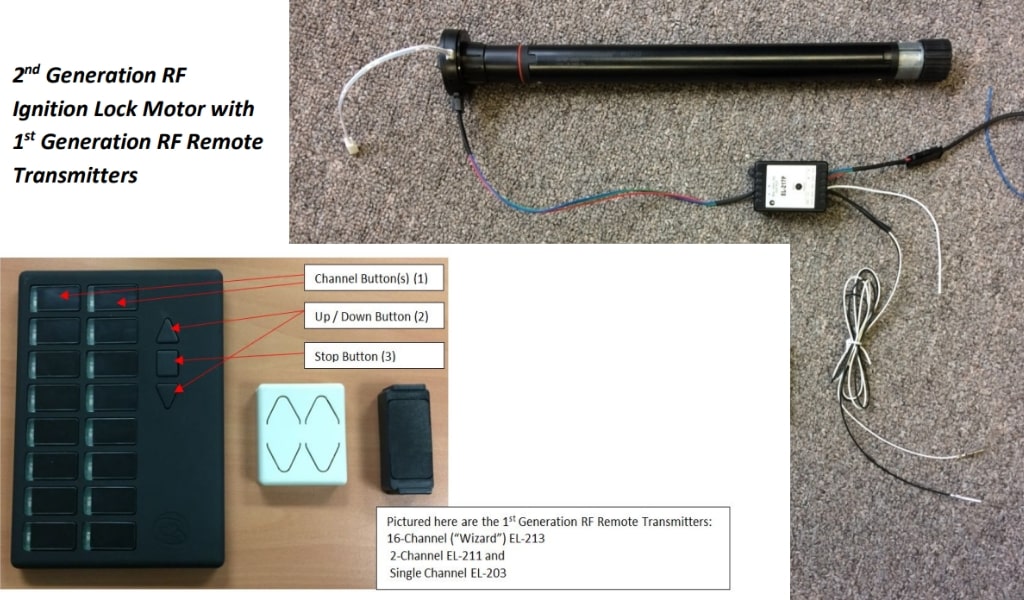
Pairing of 1stGeneration RF Remote Transmitters with 2ndGeneration Ignition Lock Motor 4270P
IMPORTANT: Ignition Lock motors are installed to enhance the safety while driving and are generally only controlled through a Dash-Switch. Operating cockpit shades by RF remote transmitter is not recommended and is only to be used in exceptional cases for drivers with disabilities who could otherwise not reach the Dash-Switch when the vehicles is parked and in “living mode”. RF Remote Transmitters are never to be used in the cockpit area while the vehicle is in motion!
This manual will guide you through the process of replacing a 1st Generation Ignition Lock Motor that is being controlled through one of the 1st Generation Remote Transmitters. The replacement motor will be a newer, 2nd Generation Ignition Lock Motor, which will need a small, separate RF Receiver Conversion Module (217P) to pick up and understand the signal sent out by the existing remote transmitter.
(Pairing of 1stGeneration RF Remote Transmitters with 2nd Generation Motor 4270P)
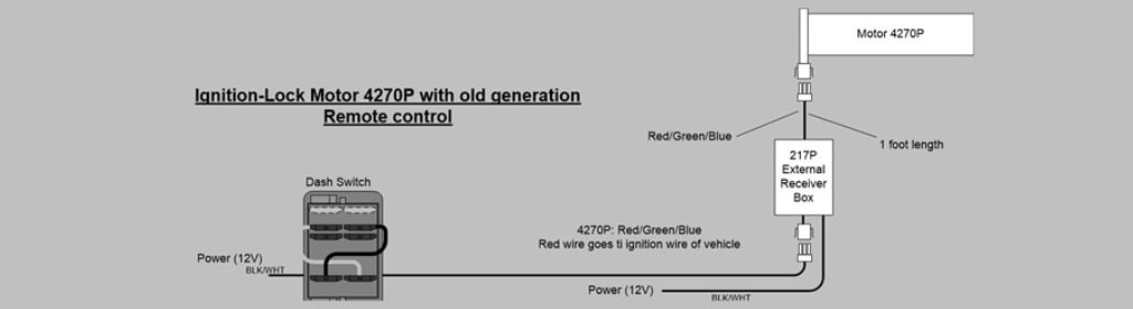
Wiring of RF Receiver Module 217P
This external Conversion Module is only to be used with old generation AMS RF Remote Transmitters.
Pairing of RF Conversion Module 217P with 1st Generation RF Remote Transmitters
-
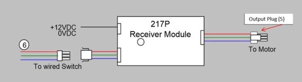
Ensure that the Module is connected to a 12VDC power supply (white wire to ground, black wire to 12V power). A green light on the Module should now be lit to indicate that the Module is ready to be programmed.
-
Now connect the Output Plug of the External Receiver Module 217P (5) to Motor 4270P.
- Follow the instructions on QRG #7-2 to set the limits on 4270P motor.
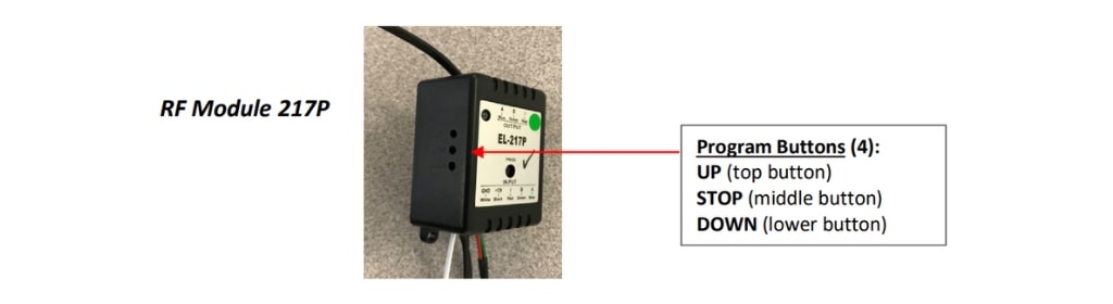
- Now locate the 3 holes on the side of 217P module for programming (4).
- On the Remote RF Transmitter, select and press the appropriate channel (1); then from the 3 programming buttons on the left side of the Module (4) select and press the “UP” button until the light turns red, then release it; while this red light is on, briefly press the “UP” button on the Remote Transmitter (2) and release it; the red light on Module 217P now turns to green.
- Go back to the programming buttons on the Module (4) and press the “STOP” button until the light turns red and release it; now press the square “STOP” button on the Remote Transmitter (3) and release it; the red light on the Module will turn to green.
- Now from the programming buttons on Module 217P (4) select and press the “DOWN” button until the red light on Module 217P comes on, then release it. Now press the “DOWN” button on the remote transmitter (2) and immediately release it; the red light on the Module will turn to green.
- Your pairing process is done and you should now be able to control your shade by means of your existing 1st Generation RF Remote Transmitter. IMPORTANT: Never press the button inside the single hole on top of 217P module marked “PROG").
If, after you have completed above paring, you should change your mind about the channel you selected, you
can clear the memory of the Module 217P to start all over again by following the below instructions (a).
Please note that the software in Module 217P was recently updated; you will recognize the updated Module by
its small green sticker on the front in which case you will have to follow instructions (b).
- Clearing of Module Memory with older software:
- In order to clear the Module memory, you will need to repeat the pairing process exactly as shown above (points 1-6), but this time by using another remote like the single channel remote transmitter (EL-203).
- You have now cleared the Module memory and you can restart the pairing process above (points 1-6) with the new channel that you selected on the original remote.
- Clearing of Module Memory with updated software:
- To clear the Module memory, the only thing you need to do is to simultaneously press the “UP” and “DOWN” programming buttons (4) on the Module and release them when red light comes on. The memory is now cleared and you can restart the pairing process as per above (points 1-6).
Note 1:
If the shade moves up when you press “DOWN” you will need to reprogram again but this time when you select the Module programming buttons as per point 4 above press “UP” while on the Remote Transmitter press “DOWN”. Then following point 5 above, press “STOP” and “STOP” on both the Module and the Remote Transmitter; and finally, following point 6 above, press “DOWN” on the Module and “UP” on the Remote Transmitter.
Note 2:
Illustration (6) shows the 3 wires with input plug coming from the Dash-Switch, connecting to Module 217P. For full wiring instructions of Dash-Switch to the Module 217P, refer to QRG #5-2.