Quick Reference Guide (QRG) #11
Last updated12 September 2023
Pairing 1st Generation Remote Transmitters with 2nd Generation Motor 4280P using External RF Receiver Module 217P
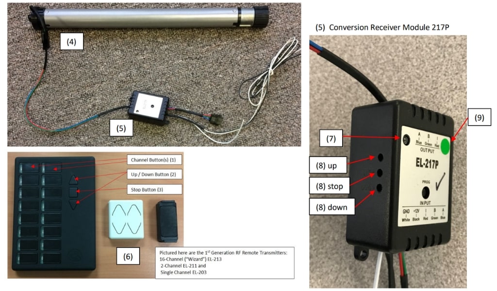
This manual will guide you through the process of replacing a 1st generation motor that has a built-in RF Receiver with a 2nd generation standard motor 4280P (4); the replacement motor will come with a special external Conversion Receiver Module 217P (5) that is able to recognize and receive the transmitter language of your existing (1st generation) remote transmitters (6). Please note that Module EL-217P is only required when combining 2nd generation motors with older generation RF Remote Transmitters, pictured below (6).
 To Optional wired Switch (*)
(*) Use only if you want a wired switch control as
Pairing 217P Module with Old Gen RF Remote Transmitters:
- Before you connect the RF module to motor, connect the motor directly to a 12V power source, like a battery, and follow QRG #2 to adjust the limit. You can swap polarity of wires to move the shade in opposite direction.
- After you have adjusted the motor limits, now connect the Output Plug of the External Receiver Module 217P to 4280P Motor.
- Ensure that the Module is connected to a 12VDC power supply (white wire to ground, black wire to 12V power). A green light on the Module should now be lit (7). Locate the 3 holes on the side of 217P module for programming (8).
- On the (16-channel) remote RF transmitter, select the appropriate channel (1), then on the left side of Module 217P press the (8) “up” button until the light turns red then release it; while this red light is on, you briefly press the triangular “up” button on the channel you selected on your remote transmitter (2), and release it; the red light on Module 217P turns to green.
- On Module 217P press the (8) “stop” button until the light turns red and you release it; following this you press the square “stop” button on the remote transmitter (3) and release it; the red light on the Module 217P will now turn to green.
- On Module 217P press the (8) “down” button until the red light on Module 217P comes on and then release it. Now press the triangular “down” button on the remote transmitter (2) and immediately release it; the red light on Module 217P will turn to green.
- Your pairing process is now done and you will be able to control your shade by means of your existing old generation RF transmitter. (Important: never press the single-hole button on top of Module EL-217P marked PROG)
If, after you have completed above paring you should change your mind about the channel you selected, you can clear the memory of the Module 217P to start over again by following the below instructions. Please note that the software in Module 217P was recently updated; you will recognize the updated Module by its small green sticker on the front (9) in which case you will have to follow the instructions as shown under b). If your Module still has the original software, you will follow the instructions as shown under a).
- Clearing of Module Memory with older software:
- In order to clear the Module memory, you will need to repeat the pairing process exactly as shown above (points 1-6), but this time by using another remote like the single channel remote transmitter (EL-203), pictured above (6).
- You have now cleared the Module memory and you can restart the pairing process above (points 1-6) with the new channel that you selected on the original remote.
- Clearing of Module Memory with updated software:
- To clear the Module memory, the only things you need to do is to simultaneously press the “UP” and “DOWN” programming buttons (4) on the Module and release them when red light comes on. The memory is now cleared and you can restart the pairing process as per above (points 1-6).
Note 1:
If the shade moves up when you press “DOWN” you will need to reprogram again but this time when you select the Module programming buttons as per Point 4 above press “UP” while on the Remote Transmitter press “DOWN”. Then following Point 5 above, press “STOP” and “STOP” on both the Module and the Remote Transmitter; and finally, following Point 6 above, press “DOWN” on the Module and “UP” on the Remote Transmitter.
Note 2:
The wiring illustration above shows the 3 wires with input plug coming from the Dash-Switch, connecting to Module 217P (10). For full wiring instructions of Dash-Switch to the Module 217P, refer to QRG 5-2.